
Reliefs, curved furniture parts, model components or sculptural carvings: 3D milling in wood produces shapes that are not possible with pure 2D machining. Unlike flat contour milling, the tool moves in several axes at the same time and follows a spatial surface. This guide explains how 3D CNC milling in wood works, which tools and strategies you need, and what matters for the machine and software.
What does 3D milling mean?
In classic 2D or 2.5D milling, the machine works in planes: contours, pockets and holes are machined at a fixed Z height or in several steps. In 3D milling, by contrast, the Z axis varies continuously: the tool follows a three-dimensional surface, such as the curvature of a relief or the rounding of a figure.
Important for context: 3D milling is not the same as 5-axis machining. Most 3D woodwork is produced on a 3-axis gantry mill, where the tool moves in X, Y and Z. Only very complex geometries with undercuts require additional axes. The difference is explained in our article 3-Axis vs. 5-Axis: Which CNC System Suits Your Requirements.
Typical Applications for 3D Wood Milling
- Reliefs and carvings: Ornaments, coats of arms, decorative wood panels
- Model making: Wing ribs, ship hulls, master patterns and moulds
- Furniture and interior fitting: Curved fronts, profiled edges, sculptural elements
- Sculptures and figures: Artistic objects, toys, decoration
- Mould making: Casting moulds and master patterns made of wood or model-making boards
Many of these applications come from model making. How to get from a one-off piece to series production is shown in the article CNC in Model Making: From One-Off to Series Production and in the practical article Model Making with a CNC Milling Machine.
The Right Tools for 3D Contours
While end mills with a flat end are usually enough for 2D contours, 3D surfaces require special geometries:
- Ball nose end mills (radius cutters): The most important tool for 3D. The spherical tip produces soft, even transitions on curved surfaces.
- Bull nose end mills (corner radius end mills): Combine a flat end with a rounded edge, and are efficient for roughing 3D shapes.
- Engraving cutters: For fine details, lettering and sharp corners in the relief.
3D work typically runs in two steps: first a larger tool removes the bulk of the material in the roughing pass, followed by the finishing pass with a small ball nose end mill for the fine surface. Which cutter suits which material and task is explained in the guide Tool Selection: Which Milling Cutter for Which Material.
CAD/CAM: From Model to Toolpath
3D milling begins at the computer. You need a three-dimensional model (CAD) and CAM software that calculates the toolpaths from it. For 3D surfaces, the toolpath strategies are particularly decisive:
- Roughing: Removing large amounts of material layer by layer
- Parallel/constant-Z finishing: Even toolpaths across the curved surface
- Step-over: Determines how fine the surface becomes: a smaller step-over gives smoother results, but a longer machining time
For an overview of suitable programs, including free entry-level solutions, see the article CAD/CAM Software for CNC Beginners.
Cutting Data and Surface Finish in 3D Milling
When finishing with small ball nose end mills, high spindle speeds are needed: only then do you achieve sufficient cutting speed with a small tool diameter, and with it a clean surface. This is where the advantage of a spindle with a high speed range shows.
How to calculate spindle speed and feed rate from the cutting speed is explained in the guide Calculating Spindle Speed and Feed Rate. The basics of woodworking, from grain direction to chip evacuation, are covered in our Practical Guide to CNC Wood Milling and the article CNC Woodworking: Where Tradition Meets High Tech.
Which machine is suitable for 3D woodwork?
For clean 3D results, the machine needs above all two properties: rigidity and precision. Because many fine toolpaths are run during finishing, the smallest inaccuracies add up visibly on the surface. A stable gantry mill with backlash-free drives and a spindle with a high speed range is therefore the basis.
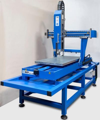
The BZT PF series covers entry into ambitious woodworking, while larger series such as the PFE series or the PFK series are designed for larger formats and productive use. Which size suits your project is explained in the article BZT PF Series in Detail. You will find an overview of all machines in the category CNC gantry milling machines.
Practical Tips for Better 3D Results
- Secure the material well: During long finishing passes nothing may move: use a vacuum table or secure clamping devices.
- Observe the grain direction: On curved surfaces the cutting direction relative to the grain changes constantly: sharp tools minimise tear-out.
- Do not choose too large a step-over: When finishing, finer is better: this saves laborious manual reworking.
- Separate roughing and finishing: A separate roughing pass protects the fine finishing cutter and shortens the total machining time.
- Evacuate chips reliably: Chips collect especially in deep 3D pockets: good dust extraction protects the tool and the surface.
Frequently Asked Questions
Can you mill 3D objects in wood with a 3-axis CNC milling machine?
Yes. Most 3D woodwork, such as reliefs, curved surfaces and model components, is produced on a 3-axis gantry mill in which the tool moves in X, Y and Z. Only very complex geometries with undercuts, where the tool has to work from the side or from below, require additional axes.
Which cutter do you need for 3D reliefs in wood?
The most important tool is the ball nose end mill (radius cutter). Its spherical tip produces soft, even transitions on curved surfaces. For rough material removal, roughing is often done first with a larger end mill or bull nose end mill, followed by the finishing pass with a small ball nose end mill. Fine details and lettering are made with engraving cutters.
Which software do you need for 3D CNC milling?
You need CAD software for the 3D model and CAM software that calculates the toolpaths from it. For 3D, the toolpath strategies are decisive, such as roughing, parallel finishing and the choice of step-over. There are also free entry-level solutions; our guide to CAD/CAM software for CNC beginners gives an overview.
Why is my 3D surface in wood not smooth?
The most common causes are a step-over that is too large (toolpath overlap) when finishing, a spindle speed that is too low for the small ball nose end mill, or insufficient machine rigidity. Blunt tools and poor workpiece fixing also lead to rough results. A finer finishing pass with a higher spindle speed and a sharp ball nose end mill usually brings the greatest improvement.
How long does 3D milling of a relief take?
The machining time depends heavily on size, level of detail and desired surface finish. The finishing pass with a fine step-over is the time-determining factor: the smoother the result should be, the more toolpaths are needed. A sensible separation into a fast roughing pass and a fine finishing pass keeps the total time within limits.




0 comments